
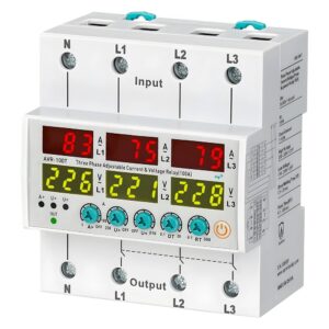
Over-current & Voltage Protection Relay 100A
In stock
جهاز عالي الأداء للحماية من التيار الزائد والجهد، مُصمم لأنظمة ثلاثية الطور بجهد 380 فولت فأكثر في الوضع المحايد. يوفر حماية موثوقة ضد الجهد الزائد والمنخفض والتيار الزائد، مما يضمن استقرار النظام ويمنع تلف المعدات. بسعة 100 أمبير، يُعد مثاليًا لتطبيقات توزيع الطاقة والأتمتة الصناعية. تصميمه المدمج وإعداداته سهلة الاستخدام تُسهّل تركيبه وتشغيله.
40,500 د.ع
In stock
Compare📖Description:
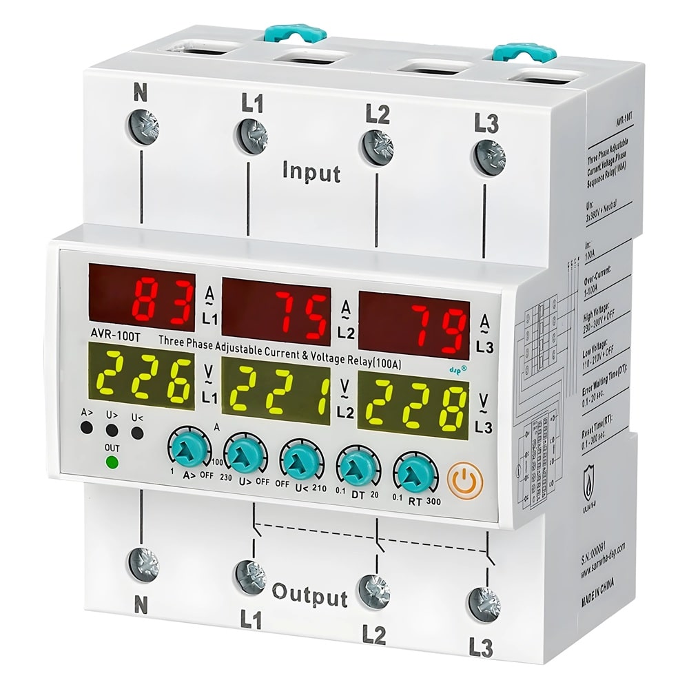
- A high-performance over-current and voltage protection relay designed for 3-phase 380V + Neutral systems. It provides reliable protection against over-voltage, under-voltage, and excessive current, ensuring system stability and preventing equipment damage. With a 63A capacity, it is ideal for industrial power distribution and automation applications. Its compact design and user-friendly settings make it easy to install and operate.
-General-
- The AVR Current & voltage protection relay is designed to protect devices with sensitive operating voltage & current values from errors that may arise from mains voltage and overload.
-Device Usage and Principle of Operation –
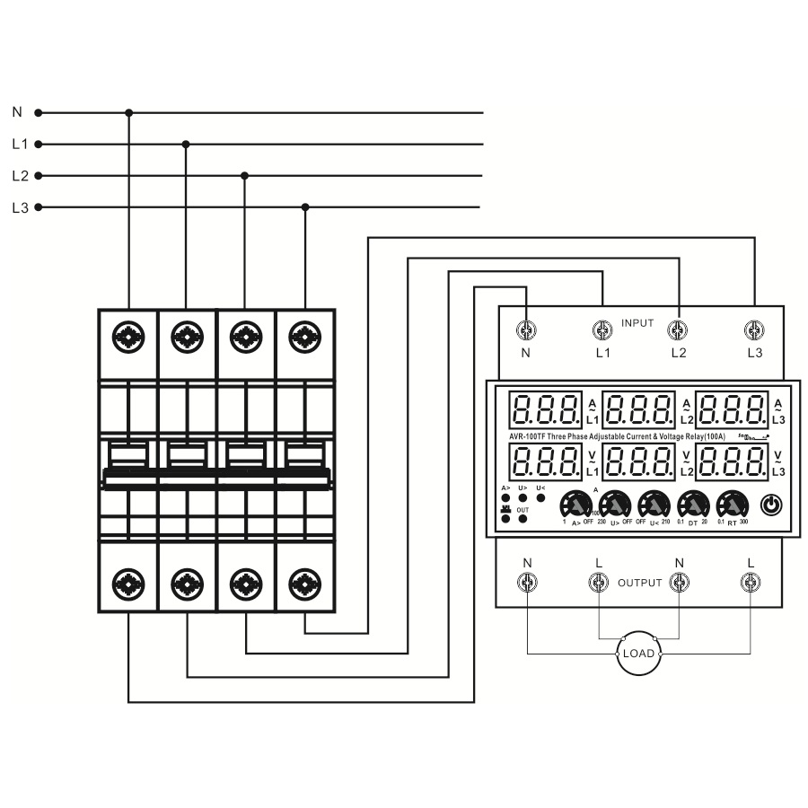
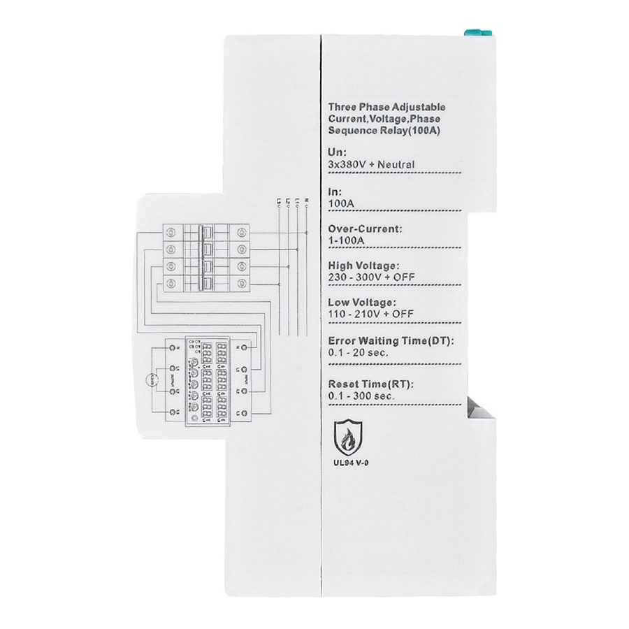
- Make the connections of the device according to the connection type. Otherwise, the device may be damaged. Adjust the over-current, high & low voltage and settings of the device according to the operating current and voltage values of the load you will use. Over-current Error state: If the current value is under the current set values (when the device is not in error), the current value rises above the current set value, the device waits for the set error waiting time, then the device de-energizes the relay, the error led lurn on, the overload value displayed on the current display flashes throughout the error period. Voltage Error state: If the mains (input) voltage value is between the high and low voltage set values (when the device is not in error), the mains (input) voltage value rises above the high voltage set value or below the low voltage set value; the device waits for the set error waiting time, then the device de-energizes the relay, the error led lurn on, the mains linputl voltage value displayed on the voltage display flashes throughout the error period. Exit the Over-current Error state: After eliminating the load over-current fault, press the on/off-key twice to manually reset or cut off the power supply. Note 1: Manual reset is to avoid secondary damage to the system by automatically resetting the system without excluding over-current or short circuits. Exit voltage error state: When the mains (input) voltage value returns to normal / when the reaches a value between the high and low voltage set values, the device waits for the set reset waiting time, then the device energizes the relay. The error led turns off, the out led turns on. A phase sequence is available on AVR-XXTF. When the phase sequence is reversed, the disallowed output and phase range (X1) led are lighted.
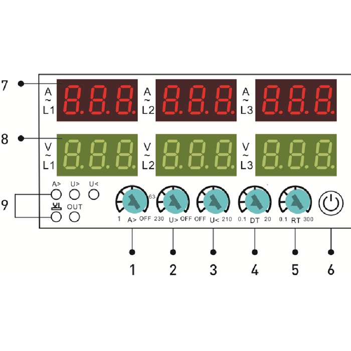
-Display and Buttons-
- 1 – Overcurrent setting knob.
- 2 – High voltage setting knob.
- 3 – Low voltage setting knob.
- 4 – Delay time setting knob,
- 5 – Reset time setting knob.
- 6 – Manual On/Off Button: To close the device output. In this state, the screen will display “off” and the device cannot be automatically reset. Press this button again to switch on the device intuse again (No failure premise).
- 7 – Current Display 1St Display Group: During normal operation, current value is displayed here. The screen lights up steadily when not in an error state.the display flashes in case of error (over-current). During the programming process, the value of the relevant program is shown on the display (Over-current and high/low volt, delay time. Reset time-setting values).
- 8 – Voltage Display 2St Display Group: During normal operation, the input voltage value is displayed here, the screen lights up steadily when not in an error state. The display flashes in case of error (high or low voltage).
- 9 – LEDs:
- A>:Light up when an over-current fault occurs.
- V>:Light up when a high voltage fault occurs.
- V<: Light up when a low voltage fault occurs.
- X1:Light up when a phase sequence fault occurs.
- ※Only the AVR-XXTF has this feature.
- 0ut: Lights up when the device starts to output.
-Working-
- Example: Set the low voltage value (U<) to 160V, the high voltage value (U>) to 260V, the delay time of (D-T) is 5 sec, and the reset of (R-T) is 10 sec. Make the connections of the device according to the connection type. When any voltage of L1, L2, L3 to N is lower than 160V, after 5 seconds of D-T setting, L1, L2, L3 turn off the output. When the voltages L1, L2, L3 to N return to the normal range, L1, L2, and L3 turn on the output after 10 seconds of R-T setting. When any voltage of L1, L2, L3 to N is higher than 260V, after 5 seconds of D-T setting. L1, L2, L3 turn off the output. When the voltages L1, L2, L3 to N return to the normal range, L1, L2, and L3 turn on the output after 10 seconds of R-T setting. AVR-XXTF type doesn’t work if the phase sequence is incorrect.
-Warnings-
- Please use the device according to the manual. Don’t use the device in the wet. Include a switch and circuit breaker in the assembly. Put the switch and circuit breaker near the device, the operator can reach it easily. Mark the switch and circuit breaker as release connection to the device.
Based on 0 reviews
Be the first to review “Over-current & Voltage Protection Relay 100A”
Related products
-
Current Protection, Sensors, Voltage Protiction
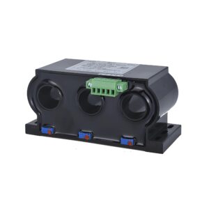
Three-Phase Split Core Hall AC Current Transmitter
جهاز إرسال تيار متردد عالي الدقة ثلاثي الطور، مُقسّم النواة، مُصمّم لأنظمة مراقبة الطاقة والأتمتة الصناعية. يُحوّل إشارات التيار المتردد إلى مُخرجات تناظرية قياسية (0-10 فولت / 4-20 مللي أمبير) للحصول على بيانات دقيقة والتحكم بها. يتميز بتصميم مُقسّم النواة غير مُتداخل، مما يُتيح سهولة التركيب دون الحاجة إلى فصل خطوط الكهرباء. مثالي لتطبيقات قياس التيار، ومراقبة الطاقة، والتحكم الصناعي.
SKU: sp29 -
Current Protection, Voltage Protiction
Over-current & Voltage Protection Relay 63ِِِA
جهاز عالي الأداء للحماية من التيار الزائد والجهد، مُصمم لأنظمة ثلاثية الطور بجهد 380 فولت فأكثر في الوضع المحايد. يوفر حماية موثوقة ضد الجهد الزائد والمنخفض والتيار الزائد، مما يضمن استقرار النظام ويمنع تلف المعدات. بسعة 63 أمبير، يُعد مثاليًا لتطبيقات توزيع الطاقة والأتمتة الصناعية. تصميمه المدمج وإعداداته سهلة الاستخدام تُسهّل تركيبه وتشغيله.
SKU: sp106 -
Current Protection
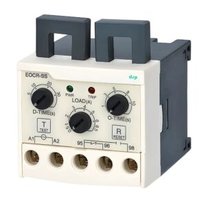
Electronic Overload Relay 0.5~6.5A
ريلي إلكتروني سهل الاستخدام لحماية المحركات من الحمل الزائد، مصمم لحماية موثوقة. يحمي المحركات من الحمل الزائد الحراري، وفشل الطور، واختلالات التيار، مما يضمن أداءً فعالاً وعمرًا افتراضيًا طويلًا. بفضل نطاق جهد التشغيل الذي يتراوح بين 90 و260 فولت تيار متردد، يوفر توافقًا واسعًا وإعدادات حماية قابلة للتعديل. تصميمه المدمج وسهولة تركيبه يجعله مثاليًا لمختلف التطبيقات الصناعية وتطبيقات الأتمتة.
SKU: sp111 -
Current Protection
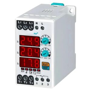
Digital Overload 0.1-25A ASYMMETRY Relay
مُرحّل رقمي للحمل الزائد وعدم التماثل مصمم لحماية المحركات. يتميز بخيارات إعادة ضبط يدوية وشبه آلية وتلقائية، مما يضمن مرونة في مختلف التطبيقات. بفضل نطاق تيار يتراوح بين 0.1 و25 أمبير وجهد تشغيل 220 فولت تيار متردد، يوفر حماية حرارية موثوقة ضد الحمل الزائد وعدم تماثل الطور. مثالي للأتمتة الصناعية وسلامة المحركات.
SKU: sp77
There are no reviews yet.